The APRS protocol traditionally employs ham radio voice channels and is therefore subjected to pre-emphasis in the transmitter and de-emphasis in the receiver. The transmitter module used on BARBE_1 however was made primarily for digital data and does not employ pre-emphasis. It is therefore up to the user (me) to add this circuit for optimal APRS transmissions. If pre-emphasis were not employed, then most likely, the quality of the APRS signal would suffer as a result of the receiver applying de-emphasis to a flat frequency signal which would greatly attenuate the 2200 Hz tone used by APRS.
Pre-emphasis design:
A 6 dB per octave pre-emphasis can be created by employing a simple first order high pass RC filter which has a roll off of 6 dB per octave on the low frequency side of the response curve. Using an Excel spreadsheet, I graphed the response curve of an RC high pass filter and played around with the resistor and capacitor values until 1200 Hz and 2200 Hz lie on the low side skirt without too much attenuation. This point occurred when the filter had a corner frequency of around 8KHz with resistor and capacitor values of 2K and .01uF respectively.
The following graph depicts those points: 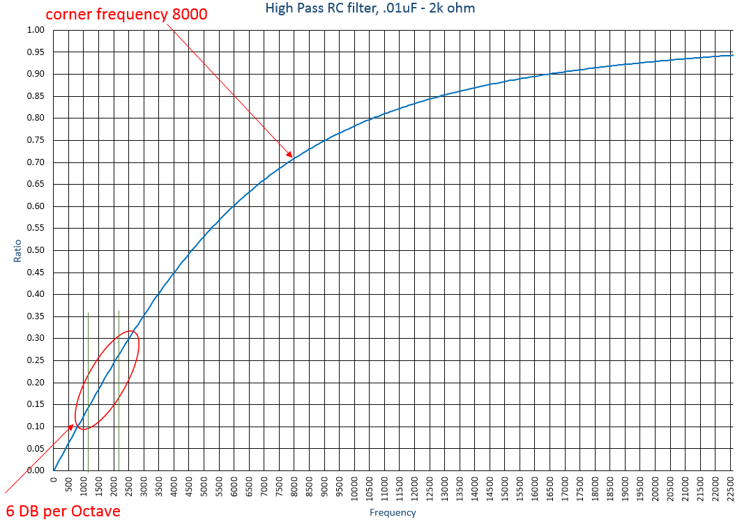 Click on graph for a larger view….
The vertical axis shows the input to output voltage ratio of the signal passing through the filter. The graph shows that the 2200 Hz tone’s voltage will be reduced by approximately 27% , and the 1200 Hz tone’s voltage by 14%. In order to recover that attenuation, I followed the RC filter with an amplifier whose gain was set to 4.1.
The final circuit looked like the following:
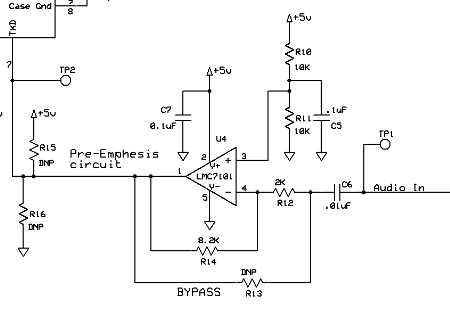 R12 and C6 form the high pass filter, while R14 and R12 program the amplifier to a 4.1 gain. R10 and R11 set the voltage offset to 2.5V.
R13, R15 and R16 are not populated but provide a means to bypass the circuit in case it did not work correctly.
To test the design, I injected 2V p-p signals of 1200 Hz and 2200 Hz to the input while simultaneously monitoring the output. These tests can be seen in the following photos:
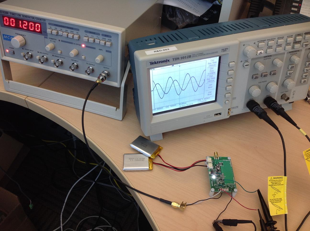
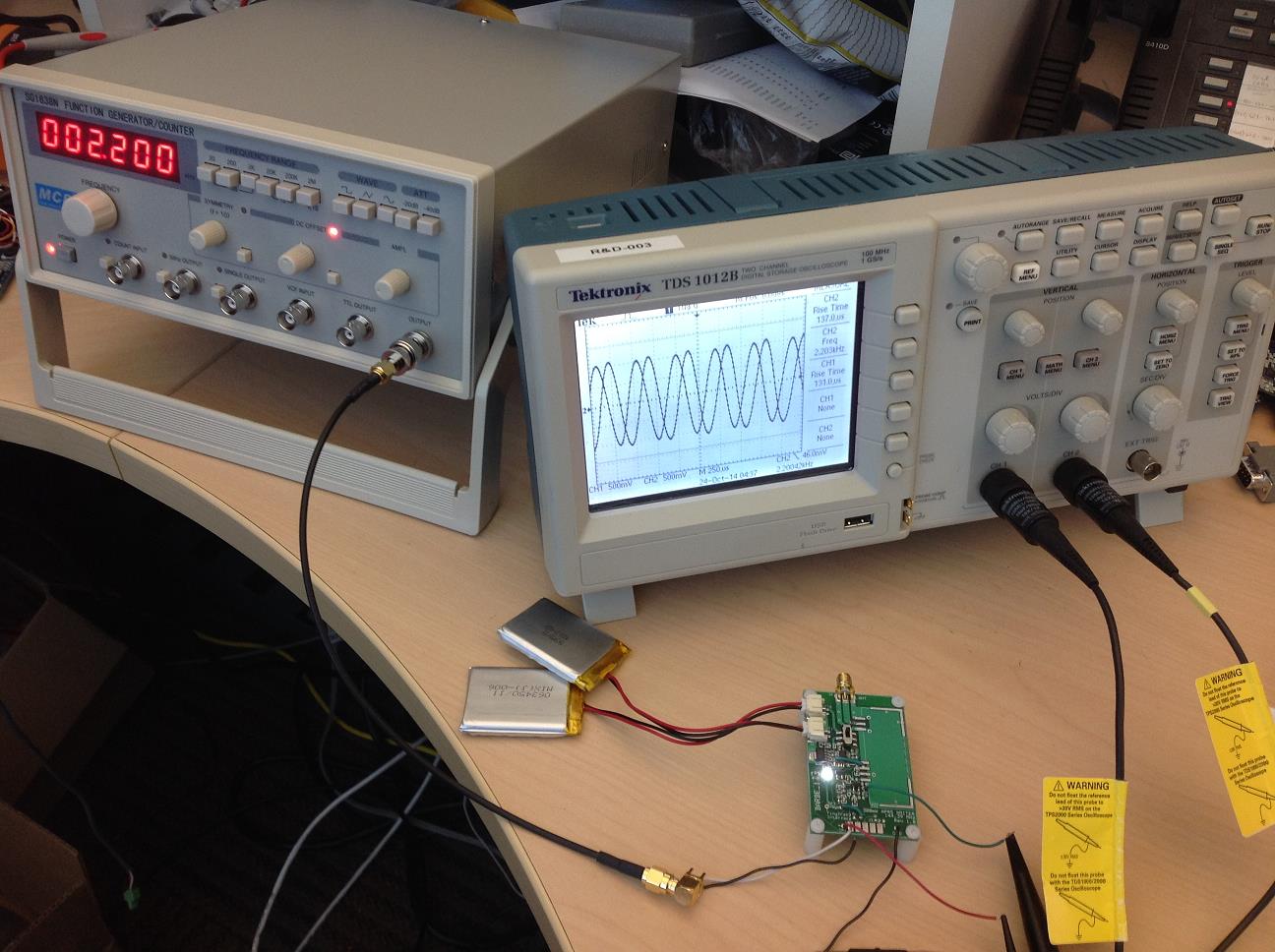
After passing through the filter, it can be seen that the 2200 Hz tone is twice the amplitude of the 1200 Hz tone which is 6db voltage gain. The 2200 Hz tone is just about the same amplitude as the input (just slightly higher). The gain required to recover the 2200 Hz tone was theoretically only 3.7 but I used 4.1 to account for part tolerances and …. just in case.
Looks like it is performing as expected!